Engineers are designing a new generation of satellite ground terminal for broadband Internet access via low Earth orbiting satellites for users on ships, aircraft or moving vehicles. This article discusses some of the challenges involved in providing ‘satcoms on the move’.
Satellite communications systems have evolved enormously over almost six decades since the first geostationary satellite, Syncom 3, was launched in 1964. This early spin-stabilised spacecraft carried just two transponders with a 2-Watt transmit power, but once the long-distance communication potential of satellites was realised, satellites rapidly became a great deal larger as many more transponders were added to the satellite payload. This in turn had significant implications for the considerable launch and operational costs involved in putting a satellite into space.
One of the earliest applications of geostationary satellites, at a time when alternative long distance communication links were not available, was television entertainment services. Such relay services enabled coverage of the Olympic Games in Tokyo to be beamed back to the United States for terrestrial broadcast in October 1964.
Scaling of satellite mass and bus power, coupled with a reduction in through-life transponder costs, enabled multi-channel TV services to be provided direct-to-home on a worldwide basis and this application is still in general use today, offering many channels of broadcast entertainment via fixed satellite communication links.
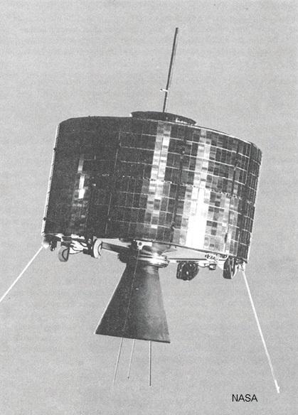 The first geostationary satellite, Syncom 3, was launched in 1964.
Simple, low-cost, mass-produced receiving terminals can be used for TV broadcast, since the high link performance needed is provided by the satellite rather than the ground terminals. And with geostationary satellites, both uplink and downlink sites are fixed relative to each other, so reception of satellite broadcasts does not require ground antenna tracking.
The Internet has further fuelled the demand for communications services for many years now, to the point where fast and everywhere-available communications are expected. Entertainment is now a very large segment of the communications market, and streaming services can be accessed to download and watch movies on mobile devices wherever cellular communications or wi-fi networks are available. Whether provided through wi-fi in buildings - or 2, 3, 4 or 5G services from cellular networks - users have become used to being able to access the Internet using their smart phones, including while mobile or ‘on the move’.
Mobile users
Users have become used to being able to access the Internet using their smart phones, including while mobile or ‘on the move’
One environment that is still evolving, however, is communications to and from mobile platforms away from terrestrial cellular systems. These platforms include ships, aircraft and large vehicles in remote areas, but even individual human beings will likely require broadband communications in future when working in remote or inhospitable areas far from terrestrial coverage networks and where video services are important.
Since geostationary satellite services have been available for many years, there are often mechanical tracking antennas on platforms such as ships and aircraft to track the satellite as the platform moves. One thing that makes this feasible is that the only movement the antenna system has to deal with is the angular motion of the platform on which it is mounted, not of the satellite itself. Pitch and roll rates are relatively slow, so the need for slewing the antenna at high rates is rarely if ever needed, as only one satellite is used.
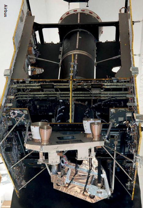 The Airbus Eurostar 3000 satellite including main satellite bus & two antennas.
But the point has come now where a new generation of satellite antenna is needed. This is because larger and larger bandwidths are needed to provide mobile broadband services for users on the move. Passengers on vessels expect to remain connected wherever they are, so a flexible means is needed for managing communication capacity demand around the world.
Many space companies are looking to address the need for a generational upgrade in satellite services. LowEarth orbiting (LEO) satellites are being launched, forming large constellations of spacecraft for global coverage. Satellites in LEO are, of course, much nearer to the ground, so the transmit power necessary from the ground terminal to support a communications link is much lower.
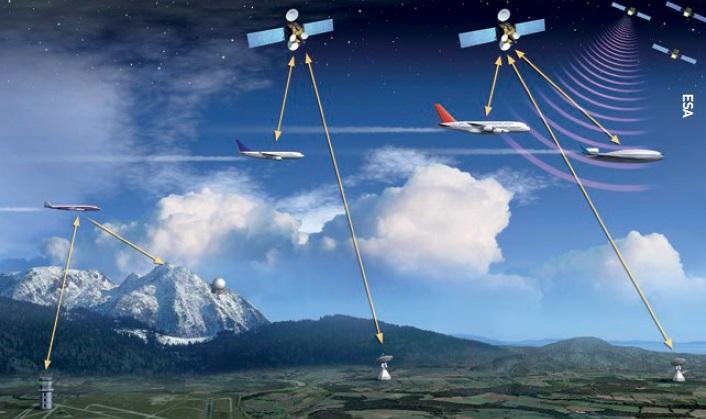 Iris - ESA’s programme for satellite communications for air traffic management.
Modern hardware
Technologies on board the spacecraft can provide hundreds of megahertz of instantaneous bandwidth and dynamically adapt to changing user needs by coverage region. The spread of communications capacity around the constellation enables the system to be flexible in allocating capacity; it can also adapt coverage to a specific territory’s requirements and continually manage both inter- and intra-system interference levels. However, the latest scenario of both the user platform moving and the spacecraft moving around the Earth means that there is a need for faster and more accurate dynamic antenna pointing technologies. This means a rethink of the traditional, mechanically steered antenna equipment.
Many space companies are looking to address the need for a generational upgrade in satellite services
With the kinds of demand on the next generation of ground terminals to link mobile platforms with low Earth orbiting satellite constellations, it is little wonder that developers are turning to electronic means for producing and steering antenna beams. Instead of a parabolic dish that is mechanically rotated in azimuth and elevation to maintain beam-pointing at the satellite, electronic antennas are being developed. Electronic beam steering can do this without moving parts and can therefore be repositioned very quickly. Multiple beams can also be generated and manipulated with the same hardware at the same time.
The technology behind this new, innovative means of producing steerable antenna beams is called a phased array. The array consists of a matrix of radiating or receiving elements in a regular pattern and typically comprises many hundreds or thousands of elements that electronically form the beam by exciting each element in a prescribed amplitude and phase relationship. The beam can then be modified by changing the amplitude and phase relationship between each element.
The radiating arrays consist of a matrix of single radio-frequency (RF) patches, whereby each point source (or phased array element) effectively replaces a point on the reflecting surface of a conventional parabolic antenna that is fed by a horn at its focus. However, the phased array offers far better control of the relationships between the sources for each of these elements than is possible in a simpler, reflector-type system (largely because it is an active, rather than passive, solution).
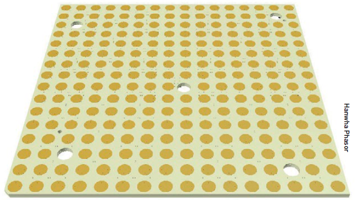 Single square array of patches on PCBs.
The complexity comes from determining in real time how the many radiating or receiving elements are fed, RF-wise, to form the beam or beams needed in real time as the antenna position and orientation changes and as the satellite constellation moves across the orbital arc.
Phased array antennas are often flat arrays, rather than profiled, and may be either circular or square, but all will be scalable to suit different platforms and mobility requirements. Design and development of these electronically steered antennas is at an early stage, although early products have reached the market or are soon to become available. Some examples of electronically steered phased array antennas specifically designed for aircraft broadband data communications are shown in the illustrations.
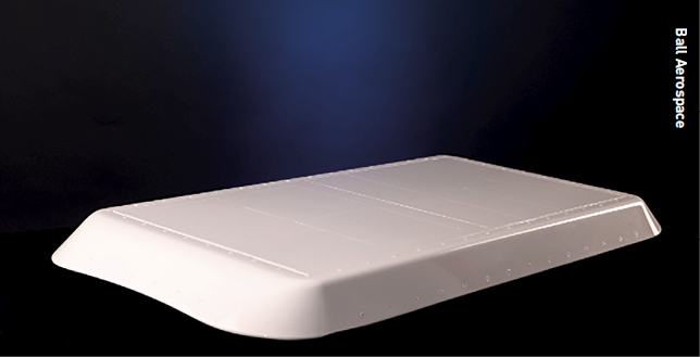 A Ball Aerospace phased array antenna for installation on an aircraft.
The challenges
With potentially thousands of radiating and receiving elements, the physical interconnections between array control circuitry and the arrays themselves can become very complex.
While the electronic solution for managing ground terminal beams is arguably the best solution available, it brings with it some significant engineering challenges. With potentially thousands of radiating and receiving elements, the physical interconnections between array control circuitry and the arrays themselves can become very complex.
Complexity and nearness of wiring can introduce the potential for coupling between different circuits and can therefore impact the size of the hardware boards to provide adequate spacing. A balance therefore has to be drawn between the performance of each array (number of beams, number of elements, element spacing and so on) and design and development feasibility to avoid cross-coupling.
Another issue that is introduced by electronic steering as opposed to mechanical steering is that, whereas mechanically steered antennas can orient themselves to physically point towards the satellite, electronic array designers are always having to manage performance off-axis (away from the direction perpendicular to the array). The reason for this is that the antenna pointing on a mobile platform is always determined by the orientation of its host plus the movement of the target satellite. This means that the design of the antenna and the management of its RF feeds has to optimise the performance of the antenna over the complete field of view.
For an electronically steered array, this field of view might be up to 65 or 75 degrees off-axis, by which point the array geometry looks very different to its aspect at boresight (the angle normal to the array). The antenna controller may then need to adapt its weighting for each feed element depending on the off-axis angle needed for pointing to a particular satellite.
However, there is flexibility in selecting an alternative satellite for transmission and reception from the number in view at any one time, which means that off-axis impacts can be actively minimised by the network and can be implemented whatever the orientation of the mobile platform.
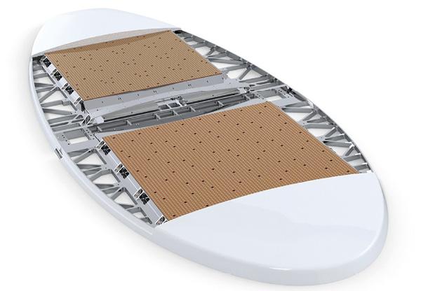 Hanwha Phasor’s Phasor A7700 satellite antenna has dual simultaneous receive channels and a single transmit channel so it can simultaneously receive from both LEO and expand MEO/GEO using a single flat antenna operating in the Ku-band.
Another factor that has a bearing on antenna performance, which is not nearly as significant for traditional parabolic antennas, is the radome. In harsh environments, such as on an aircraft or at sea, a radome is needed to provide protection to the hardware from wind, rain (or salt at sea), or from bird strikes, hail, dust and other harsh conditions in the air. With mechanically steered antenna radomes (familiar to us all as a ‘golf ball’ at satellite ground stations or onboard ships), the beam from the antenna is looking normal to (straight through) the radome, so the radome’s impact on the antenna transmission is minimal. The radome would merely introduce insertion loss that can be taken into account in the RF budget.
The design of the antenna and the management of its RF feeds has to optimise the performance of the antenna over the complete field of view
With electronic steering, however, the beam off-boresight will often be looking through an increasing thickness of radome material as the off-axis angle increases. Thus, since radome materials commonly have multiple layers to produce a suitably robust material to protect the antenna physically, the RF performance at increasing angles of incidence needs to be carefully characterised and accounted for.
Beam pointing is also a considerable challenge. Generally speaking, the larger the vessel the slower the angular rate of change in roll or pitch. Whereas a large container ship will only be rolling and pitching a few degrees per second, a commercial aircraft could be rolling or pitching at ten times this angular rate and a small vehicle several times that again. Having an accurate local reference source for the position and orientation of the platform will be necessary. The refresh rate of this information fed to the antenna will also need to be considered. Too slow and the antenna beam will lag behind the satellite to which it should be pointed, which will degrade the pointing error budget.
Highly accurate data concerning the orientation and position of the antenna is therefore necessary. This data set is fed to the antenna controller, which will need to combine this with the real-time positions of satellites overhead, supplied by the satellite operator. It will only be through combining these data sets that the antenna will be able to work out where to point its beam or beams and the rates needed to keep pointing vectors updated as both the platform and satellites continue to move with respect to each other within the fields of view.
 Example of mechanically steered satellite antennas on a ship to provide VSAT communication.
As in the case of the roll rates above, if the processing of attitude and ephemeris information is too slow, the beams will not be adequately pointed at the spacecraft and the link quality will be degraded. With a pointing error target of the order of a few tenths of a degree, the cumulative impacts of these and other sources of pointing error can represent a serious challenge to design engineers.
With the need for complex beam steering computation across each array, there is inevitably a need for high power levels to supply the many active elements needed to produce the characteristics and orientation of the antenna beam or beams. Such power demands can be difficult for some mobile platforms to supply and regulate, so this needs to be factored into the choice of components and their variability over the working environment.
Lastly, with a very complex system of feed elements, beam control and component variability, there is a need for accurate calibration of the terminal. With in-service periods of a number of years, a method needs to be found for calibrating the antenna and its feed system - both at the start of life and potentially at various points while in service - depending on component drift rates and magnitudes.
Rigorous approach
A number of innovative companies are working on the leading edge to solve these significant engineering challenges, and a new generation of communication system is coming to the market
This article is by no means intended to cover all of the challenges that systems engineers face in implementing a phased array antenna on a moving platform, simply to point out some of the key technical challenges where innovative ideas for design solutions are needed.
In general, careful management of performance requirements and performance verification are needed throughout the design and development process - taking product requirements and translating these into how the system is going to perform in a very dynamic communications-on-the-move scenario.
Unless a rigorous approach is taken to systems engineering and test - throughout the ground terminal design phase - vital factors affecting the performance of the link could be omitted and performance compromised. Indeed, it will only be when phased array antennas are deployed on a number of moving platforms, and communications link performance demonstrated in the field, that the market will open up to this new generation of flexible, adaptable and ultimately high-performance satellite terminal product.
On the positive side, a number of innovative companies are working on the leading edge to solve these significant engineering challenges, and a new generation of communication system is coming to the market for broadband communications to and from mobile platforms. They promise to provide broadband communication services on the move, everywhere, all of the time.
About the author
Roger Dewell is Managing Director of the satellite systems consultancy High Q Systems Ltd. Having worked in the space industry for more than 50 years, Roger has design, development and engineering management experience related to many advanced civil and military satellite systems around the world. More recently, he has provided technical and business development support for a number of smaller space companies seeking to grow their businesses.


